10.5 MECHANICAL INTEGRATION OF ENGINE SYSTEMS
Basic Considerations
Besides combining all components and subsystems functionally and physically, the design for mechanical integration of an engine system must consider the overall envelope of the system and its weight. This includes the location of the system's center of gravity. Also, it should permit simplified maintenance and checkout practices. Judicious packaging design techniques should be applied to minimize the number of interconnecting hydraulic, pneumatic, and electrical lines, with their attendant fittings, connectors, joints, and other potential trouble spots. Welded and brazed joints should be used as much as possible. Problems introduced by vibration, high temperatures and pressures, leakage and space restrictions are thus more easily handled. Engine mechanical integration is a vital part of the system design concept; therefore, all factors related to integration and packaging of components and subsystems must receive careful consideration early in the preliminary design stage.
In general, a modular engine packaging approach should be selected such as used for the A-1 (fig. 3-2) and A-2 (fig. 3-4) stage engine systems, as well as for many advanced operational engine systems. This assures engine integrity from time of manufacture through vehicle launch. It also provides a compact package for ease of handling, transportation, and installation in the vehicle. Ease of checkout and component accessibility is also afforded by the packaging concept.
The engine should be completely assembled in the manufacturer's plant. Subsequent acceptance testing, air transportation, and installation in the vehicle in the field should not require assembly of additional major components. Integrity of the propellant feed and hot-gas systems, once verified in a complete system during acceptance test, is not necessarily nullified by the need to temporarily disassemble the engine for shipment. The integrated engine package concept provides added assurance that static teststand firing results have verified structural soundness of the package to a substantially greater degree, than is the case for a system where the vehicle provides portions of the engine structure.
An example of a special case of mechanical integration of a liquid propellant rocket engine is the prepackaged storable liquid rocket propulsion system shown in figure 8-1. This system is a completely integrated assembly of all-welded construction, consisting of thrust chanber assemblies, propellant tanks, pressurization system, and necessary controls. This provides maximum assurance of system integrity from the time of manufacture, which includes loading of the propellants, through delivery, vehicle assembly, and launch. Complete propellant separation until systems start is achieved by hermetically sealed burst diaphragms for maximum safety. Acceptance tests are conducted by taking sample units at random from the production line, and hot firing them. In addition, destructive tests of various types are performed.
Packaging of Rocket Engine Components
Most major rocket engine components, such as thrust chamber (fig. 4-1) and turbopump (fig. 6-14) assemblies, readily form a logical, independent mechanical unit by virtue of their function and their physical shape. However, in the case of minor components such as control valves, gas generators and igniters, packaging design principles can best be served by making them an integral part of a major component assembly, or to integrate them by grouping. A typical example is a gas generator assembly externally attached to a turbine inlet flange (fig. 3-2). Similarly, gas generator propellant valves and combustor can be integrated into one unit (fig. 4-51).
Certain types of hydraulic and pneumatic rocket engine control components lend themselves most conveniently to the packaging design. Here, one of the main objectives is to reduce line runs, by combining all parts and passages into one housing. Such a housing (or mounting plate) is relatively leakproof, trouble areas now being limited to external line connections to other components. Furthermore, if components are packaged in this manner, reductions of weight and size are achieved through the use of common walls and through the elimination of extra mounting platforms, clamps, and fasteners. Since relatively few packages are required as compared to the usually large number of individual components, maintenance of such a system is greatly simplified. Integrated packages are about as easily removed and replaced as are the separate components making up each package. However, the packaged design is not necessarily desirable for every control system. Each case must be carefully studied.
As a rule, one or a combination of the following methods is used for packaging engine control components: (1) Bank packaging: A group of similar flatsided component assemblies are bolted together in a bank or stack, with common porting through the mating surfaces from one unit to the next. (2) Subplate packaging: Attachment of two or more individually housed components to a subplate, so that all ports of the individual component housings lead into the subplate manifold, through their mating surfaces with the subplate, and on to the systems plumbing. (3) Cartridge packaging: Two or more components housed individually in cylindrical cartridges are in turn assembled in a common body with suitable manifolding to the systems plumbing. (4) Multiple-component packaging: Detail parts for two or more components are assembled in a normal fashion in a common housing or body. Figure presents a typical pneumatic control package for a large liquid propellant rocket engine. This package combines two pressureregulator assemblies, two relief valves, a series of solenoid valves, filter units, and check valves. It controls the flow of helium gas to various engine components. When engine start is initiated, the helium control solenoid is energized allowing helium to flow through the main pres- sure regulator to the control system. The helium is routed internally to the main control valves through a fail-safe check valve. This insures that the various engine propellant valves remain pressurized and thus open, should the helium gas supply system fail.
Packaging of Turbopump Feed Engine Systems
In earlier high-thrust rocket propulsion systems, some of which may still be in operational use, all major engine components were mounted into a cage-shaped thrust mount, which was bolted to the vehicle thrust frame by way of lugs. Figure 2-4 shows several typical examples. With these systems, vehicle steering was accomplished by means of carbon jet vanes protruding into the jet (V-2 and Redstone), or by swiveling the thrust chamber (Thor, Jupiter). In the latter case, the high-pressure feed lines between pumps and injector had to be much more flexible than for misalinements and thermal expansion/ contraction alone.
Most advanced liquid rocket engines are tightly packaged. All major components are attached to the main thrust chamber, directly or by means of mounting structures, as shown in figures 3-2, 3-4, and 9-1. Here, the thrust chamber serves as the principal structural member of the entire engine system. For steering, the complete engine package is gimbaled from a gimbal bearing which attaches directly to the thrust chamber dome. The other half of the bearing is attached to the vehicle thrust structure. The low-pressure propellant supply ducts must be sufficiently flexible to accommodate the gimbal motions. It is noted that vehicle steering through gimbaling of a single engine or chamber is effective only for the pitch and yaw planes. For roll control, at least two engines are required. For vehicles with a cluster of engines, therefore, this poses no difficulties. For single-engine vehicles, special roll-control devices are needed. These may be small auxiliary nozzles, possibly simultaneously used as vernier engines after main-engine cutoff. The use of the turbine exhaust for roll control has also been proposed.
Whether the engine attaches to the vehicle thrust structure by means of a thrust frame or a gimbal bearing, either device must be designed to be capable of transmitting the full thrust
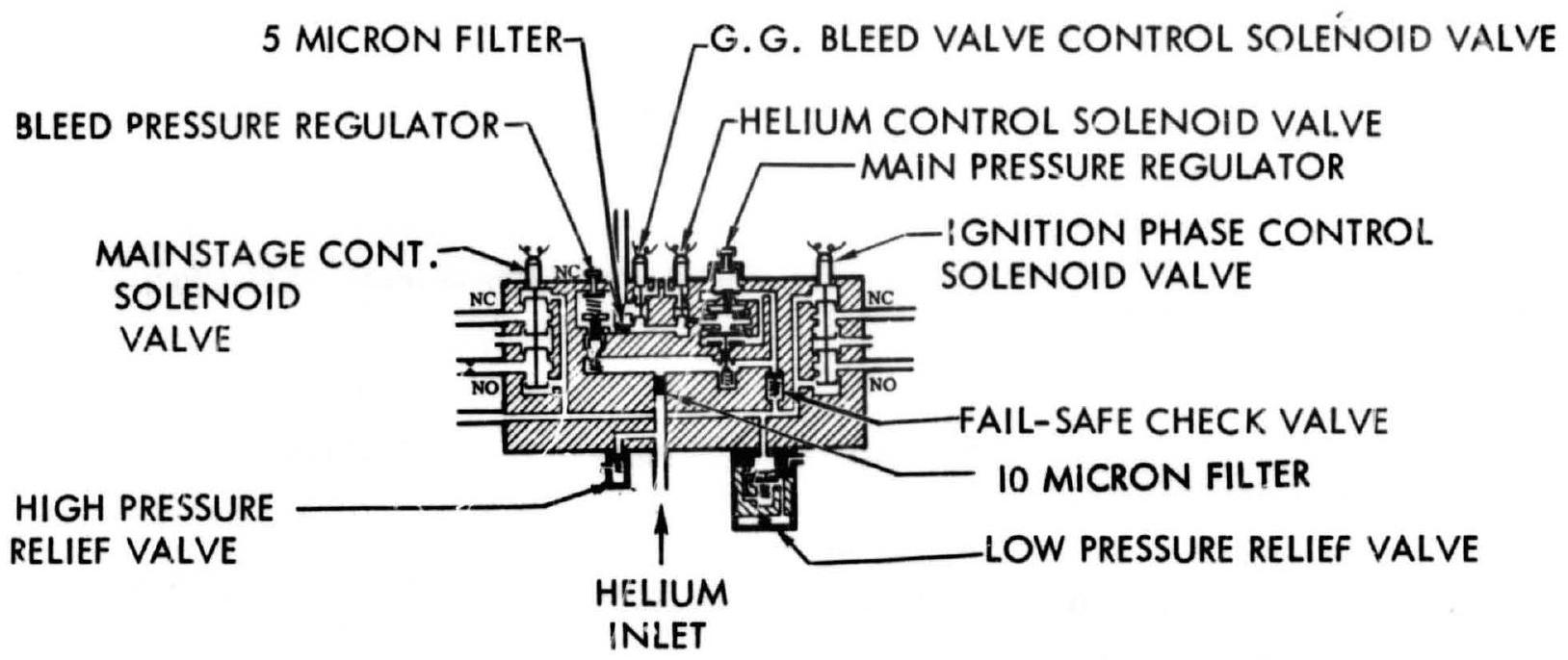 PNEUMATIC CONTROL PACKAGE SCHEMATIC
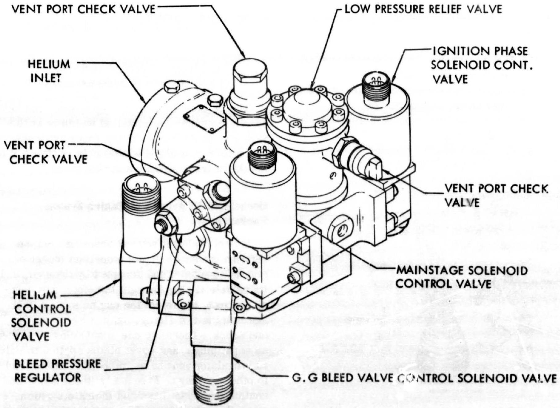 Figure 10-9.-Typical pneumatic control package design used in liquid propellant rocket engine systems.
forces at full gimbal deflection, including an adequate reserve for normal and for side loads. The bolt-hole pattern must permit adjustment for tolerance deviations. In general, engine and vehicle attachment halves must be designed for one another.
Figures 10-10 and 10-11 illustrate the packaging design details of a typical pump feed system. It is a , fixed-thrust engine with constant chamber pressure control. The basic engine package consists of the following subpackages: (1) Gimbaled main thrust chamber assembly (thrust chamber, injector, dome, oxidizer elbow, and gimbal mount) (2) Turbopump assembly (propellant pumps, turbine, gearbox, lube pump, electric heater, auxiliary drive) (3) Gas generator assembly (combustor, control valves, regulator and turbine inlet duct) (4) Main oxidizer duct assembiy (including main oxidizer valve) (5) Main fuel duct assembly (including main fuel valve) (6) Turbine exhaust duct assembly (including heat exchanger) (7) Engine start subsystem (oxidizer and fuel tanks, control valves) (8) Turbopump lube subsystem (lube oil and fittings) (9) Pneumatic control package
 Figure 10-10.-Major component and subsystem paciages of turbopump-fed liquid propellant rocket engine.
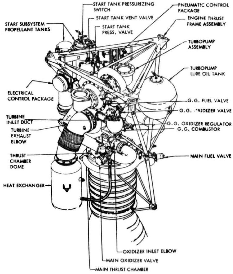 Figure 10-11.-System packaging design detail of the engine shown in figure 10-10.
(10) Electrical control package (11) Engine thrust frame assembly
The majority of the major compornt and subsystem packages are installed within or at the periphery of the engine thrust frame assembly. The main thrust chamber assembly is attached to the thrust frame through a gimbal mount.
Mechanical Protection of Engine System Packages
It is normal that several years may elapse between the date a liquid propellant rocket engine is completed and accepted by the user, and its vehicle flight. Design, therefore, must consider means to protect the engine system package in transit or storage against moisture, dirt, and shock. These include simple closures, such as caps, plugs, and cover plates applied to valve and regulator vent holes, propellant inlets, and to other openings. Frequently, these closures contain desiccant bags and indicators which warn, through change of color, of undesired intrusion of moisture. Certain lines, however, may require communication with the ambient air
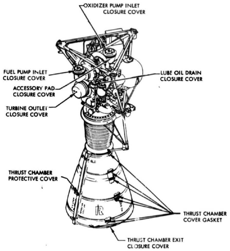 Figure 10-12.-Various protective closure covers for the engine shown in figure 10-10.
("breathing"). In this case, the closures may be equipped with desiccant filters to permit access of dry air only. Some of the covers must be removed for installation of engine to vehicle. Others will be left in place until the engine is actually operated. These must be readily accessible and clearly marked, such as with bright colors, to prevent their being left in place inadvertently. Figure 10-12 shows the location of various protective closures for the Rocketdyne LR79-NA-11 engine.